MAKE A MEME
View Large Image

| View Original: | Car ignition and steering wheel lock.png (324x239) | |||
| Download: | Original | Medium | Small | Thumb |
| Courtesy of: | commons.wikimedia.org | More Like This | ||
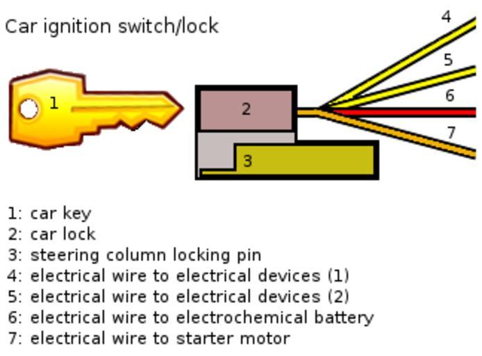
| Keywords: Car ignition and steering wheel lock.png en A schematic showing the ignition/steering wheel lock of a car Note that the 4 wires are not connected from a single wire they are seperate the schematic was made how it is because I wished to clarify that they run next to each other rather than under each other when viewed from the side Note that 4 is generally connected to the largest power consumers ie main lights rear window heater windscreen wipers cigarette lighter 5 generally connects to smaller power consumers Note also that most car ignition/steering wheel locks also have 4 modes <br> In mode 0 main engine is off or is stopped if the engine was already on 4 5 7 are not connected to 6<br> In mode 1 4 is connected to 6<br> In mode 2 4 and 5 are connected to 6<br> In mode 3 4 5 and 7 are connected to 6; note that this 3rd mode is springed meaning that the key will spring back to mode 2 upon release of the key This is because the powering of the starting engine is no longer wanted once the main internal combustion engine has kicked on <br> The schematic was made based on the http //commons wikimedia org/wiki/File KEY png image and by following a schematic from the book Zo werkt uw auto by Rien Tholenaar and Carel Zaal own KVDP 2010-07-17 Automobile parts Ignition systems | ||||